With advancing process technologies and the booming development of AI, memory demand has steadily increased. In this context, memories with repair functions have become increasingly important. However, if a memory does not originally include a built-in redundancy block, it cannot be repaired when faults occur and must be discarded. To address this issue, STARTTM v5 offers a corresponding solution: by leveraging the Stand-Alone feature, redundancy blocks can be generated. These blocks enable fault repair for memories that originally lacked redundancy. Additionally, users can customize the size of the redundancy block to fit specific design requirements.
Stand-Alone Repair Architecture
As shown in Figure 1, the architecture is similar to the previous MBIST setup, with the key addition of a redundancy block. This block is used to replace faulty SRAM addresses. Through MBIST, SRAM is diagnosed, and the fault information is stored in the TRA. The TCR is used to perform switching; it manages the switch between system and BIST operation. This ensures that during normal system operation, when a faulty address is accessed, the system can still perform repair.
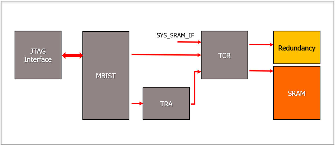 Figure 1 Stand-Alone Repair Architecture
Tool Setting
Stand-Alone Repair requires the user to first fill out the rmt (redundancy mapping file), which describes the memory hierarchy for Stand-Alone repair and the corresponding memory repair information. A sample file is shown in Figure 2. If the redundancy memory hierarchy is set to istart, the tool will automatically generate the corresponding redundancy module for that memory, eliminating the need to manually write redundancy circuits.
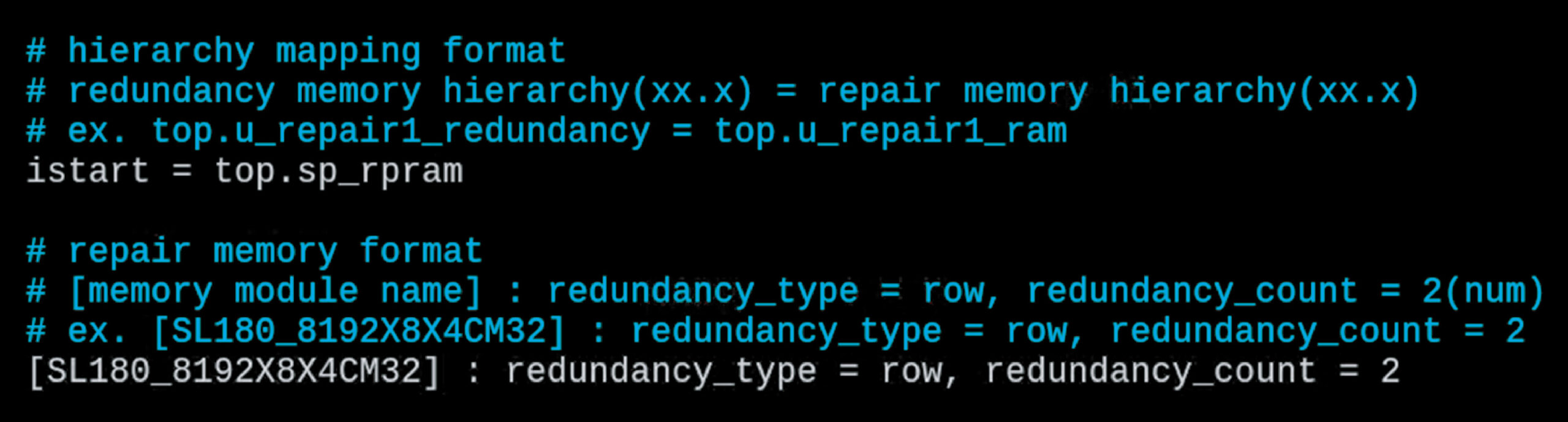 Figure 2 Example of rmt (redundancy mapping file)
After writing the rmt file, the user must configure the options shown in Figure 3 within the BFL settings file.
![]() Figure 3. BFL Options
Figure 3. BFL Options
Simulation Method
The tool will generate the corresponding fault module. Since both regular memory and memory with redundancy will coexist during simulation, the REPAIR definition must be enabled to ensure that the fault module generated by our tool only affects the Stand-Alone memory.
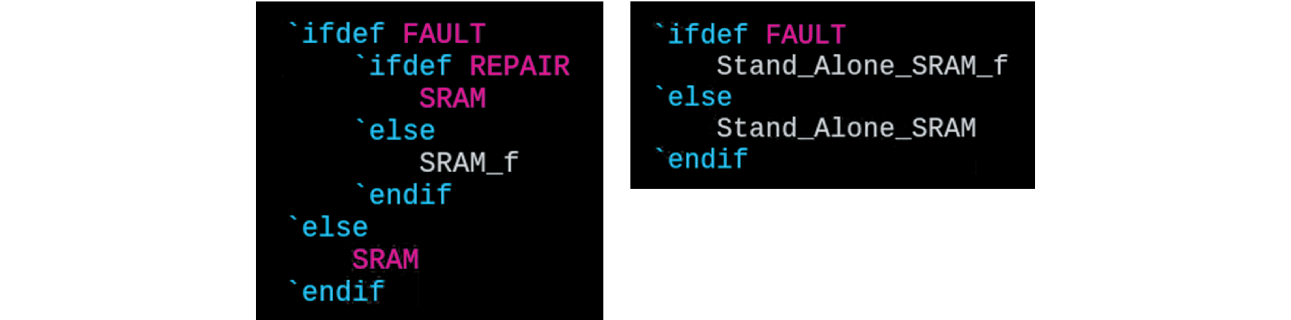 Figure 4 Fault Module Definition
Our flow consists of BFL and BII stages, both of which generate the corresponding simulation environment. Simulation commands and results for the BFL stage are shown in Figures 5 and 6, and those for the BII stage are shown in Figures 7 and 8.
![]() Figure 5 BFL Simulation Command
Figure 5 BFL Simulation Command
 Figure 6 BFL Simulation Result
![]() Figure 7 BII Simulation Command
Figure 7 BII Simulation Command
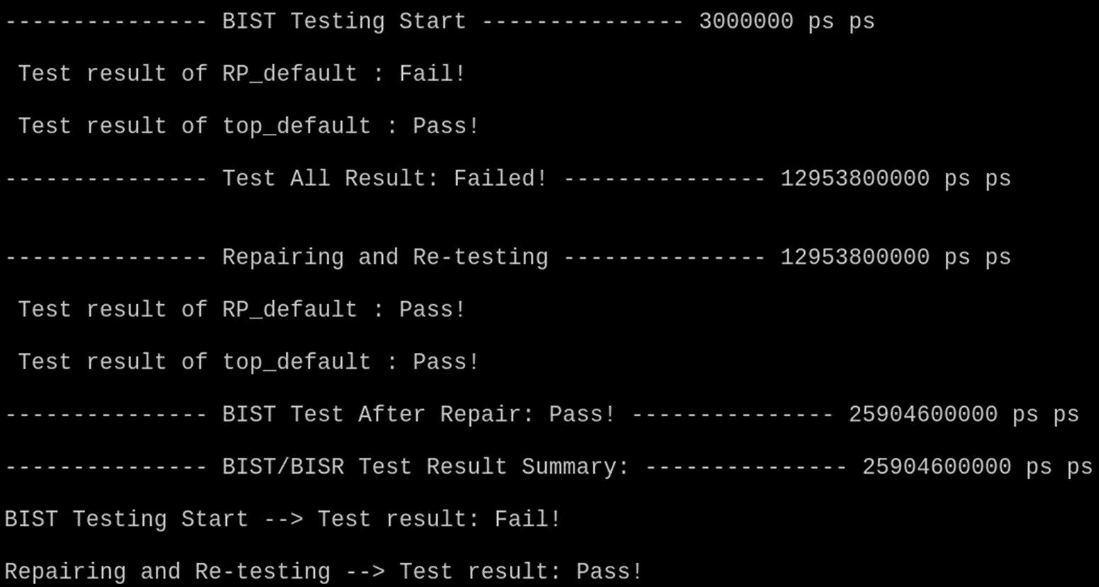 Figure 8 BII Simulation Result (Soft Repair)